Boiler
A boiler is a closed
vessel in which water or other fluid is heated under pressure. The fluid is
then circulated out of the boiler for use in various processes or heating
applications. Boiler is the most important part of the mill as it is the main
station for generating steam and aiding the operation of turbine in the engine
room. There are 2 boiler in the mill, the capacity of the 1st boiler
is 45mt/h and the empire boiler is 40mt/h. The both boiler are water tube
boiler type. The water are circulates in the tubes and heated externally by the
fire. The fuel is burned in the furnace, heat up the water in the steam
generating tube. The water from the water drum will flow to the mud drum to be
heaated. The water tubes are lines on the wall of the furnace to generate
steam. The heated water then rises to the steam drum.
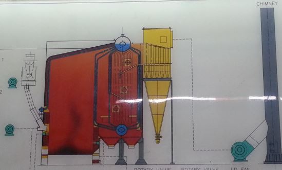
Figure 1: 1st Boiler layout
Fans
Force draft fan (FD fan)
-Blow the air from the bottom of the furnace
floor. The air is blow through the furnace floor holes for the burning of the
fibre.
Induced draught fan (ID fan)
-Induced draft is to flow the air by the effect
decreasing the air pressure.
Fuel feeder fan (FF fan)
-to sweep the fibre out from the chute inlet to
feed the fibre into the furnace and prevent fibre from clogging at the inlet
chute.
Secondary fan
-locate on the wall of the furnace below the
fibre feeder chute. It is use to blow the fibre to allow evenly distribution of
the fibre throughout the fibre.
Frequently check the
ampere reading of all the fans to make sure the fan is working at optimum
condition. Incorrect condition of the fans will affect the combustion in the
boiler and may lead to boiler trip.
Factor to achieve
good combustion
1. Time
Time required for the
fuel to totally burn in the boiler furnace. If the time is too short, it can
cause the fuel not being burn properly and the chemical energy cannot be change
totally. Fuel which does not burn properly will cause clinker in the furnace
and came out through chimney.
2. Temperature
For proper combustion,
temperature in the boiler furnace must be at optimum level so that the
temperature can burn the fuel that being feed to boiler furnace. Low
temperature can cause the fuel not properly being burn and came out from the
chimney. The suitable temperature should be 260 degree Celsius and above.
3. Turbulence
Turbulence is being
produce by the fans such as Fuel Feeder Fan, Secondary Air Fan and Force
Draught Fan. Fuel will be feed to the boiler furnace using Fuel Feeder Fan and
being distributed by Secondary Air Fan to all part of boiler furnace. During
distribution process, most of the fuel is being heated up and burn to produce
heat energy.
13 essential fitting
(Safety)
1. Safety valve
-prevent excessive
pressure buildup in the boiler which could lead to boiler explosion.
-view release the steam
when the pressure reach the limit (460psi)

Figure 7: safety valve
2. Water gauge
- to indicate the water
level in the water drum

Figure 8: glass gauge

Figure 9: water gauge
3. Steam pressure gauge
-measure steam pressure

Figure 10: steam pressure gauge
4. Fuse plug (not using in the boiler for this mill)
-low water protection,
when the water level is low, the fusible plug will melt, the pressure inside
the boiler is released and produce high whistling sound
5. Low water alarm
-give warning on low
water level

Figure 11: The water level display on the
board.
6. Low water fuel cut out
-prevent boiler over
heating failure, in the event of low water level, every valve, fibre conveyor
and fan will be cut off.
(Control)
7. Blow down valve
-For boiler water blow
down to control boiler water TDS
-Use in the event of
high TDS in the boiler water or high water level in water drum.

Figure 12: blow down valve
8. Feed pumps
- Feed water from the
deaerator into the water drum
-Feed pump need to have
enough capacity to overcome the pressure of the steam in the water drum

Figure 13: double feed pump
9. Mainstream stop valve
- Allow the flow of the
steam

Figure 14: Mainstream stop valve
10. Feed check valve
-control the flow of
the water from feed pump into water drum
-ensure single
direction flow of the water

Figure 15: Feed check valve
(Legal)
11. Inspector test pressure gauge attachment (not attaching to the boiler)
-for double check of
pressure gauge function, pipe leakage
-hydraulic operated
12. Manufacturer name plate
-Record the
specification of the boiler such as working pressure, testing pressure, working
tempeature, design code, date of built of the boiler.

Figure 16: Manufacture name plate
13. Registration plate
-Registration number of
the boiler

Figure 17: registration plate
Vacuum Deaerator
The vacuum deaerator
functions to reduce and eliminate gases such as oxygen, which can corrode the
boiler tube and steam drums.
The water is feed into
the deaerator from the feed tank by gravity. The water is splash up through the
nozzels. Steam is supply on the top line and created a vacuum condition that
remove the oxygen in the water. The deaerated water will fall to the bottom of
the deaerator and flow to the feed pump.
O2 is removed by
creating Vacuum using steam jet.
• In vacuum (-20 inHg),
water boiling point is lowered (60-70 degree celsius)
• Have to prevent air
in-leakage into the system through pump, seals, valve, fittings, flanges of
gauge glass.
Figure 18: deaerator
Figure 19: Vacuum deaerator working principle
Softener
Softener is a machine
that functions to soften the water by reducing the content of calcium and
magnesium in the water with the help of resin with polystyrene beads that carry
negative charge. Salt diluted with water will be added into the softener to
regenerated the resin after resin exhausted. One boiler require 2 softener to
run. The softener will receive the water supply from the overhead tank and
supply to the hot water tank after processed.
Operating procedure
Before:
1. Check the condition of the boiler including the pump, pipe, fan, stone
platform, furnace interior and any record of the problems of the boiler that
happened the day before. If there are any, the problem should be fixed before
starting the boiler
2. Check and ensure that the water level indicated by the gauge glass is
one third full.
3. Check the gauge glass and steam pressure on the boiler.
4. Check the condition of the steam stop valve, blow down valve and the
drain valve. Ensure they are tightly closed and not clogged.
5. Ensure that the water level in the overhead tank and boiler feed tank
are always full.
6. Check softener and vacuum deaerator.
7. Open the air cork, super heater and steam trap.
8. Turn on the the induced draught fan (ID Fan) before filling fibre and
shell
9. Check whether the boiler feeding chute is not clogged..
10. Control the amount of fibre and shell goes into the furnace at the
initial until the steam pressure reached 400psi. Too much fibre and shell pile
up on the floor will stop the combustion.
During:
1. Check and ensure the water level indicated by the gauge glass is below
1/2 level.
2. Control the steam pressure at 420 psi.
3. Ensure the fibre cyclone airlock, fibre conveyor, fibre return feed
conveyor and boiler feeding chute is not clogged.
4. Clean and remove the fibre from the furnace every 4 hours to prevent the
fibre pile up.
5. Rcord the drum pressure, water level, temperature, deaerator pressure,
ID fan, FD fan every hour.
Possible incident
1. Furnace collapsed
Cause: furnace overheat
Prevent: ensure the water level are maintained at 60-70% in the process
and no tube
blockage.
2. Sand blasting effect
Cause: Too high draft
that affect sand blasting on the tube
Soot blower nozzle misaligned
Preventive:Balance the
ID fan to the furnace
Check the soot blower nozzle
frequently
3. Tube dislodge and distort due to overheating
Cause: Overheating on
the tube due to low water level
Preventive: Check the
low water alarm
Check auto level controller
system
Ensure sufficient pump capacity
Usual incident in
the process
1. Low water level
- turn on the bypass
valve to allow the water to bypass the regulator.
2. High water level
- use the blowdown
valve to drain out the excess water
3. Fibre inlet chute blockage
- need to monitor it
all the times to make sure the chute are not clogged.
Boiler trip emergency
1. Power disruption
-close off the main steam stop valve
-ensure there is water in the water drum
-open the ID fan damper and the bottom ash
doors
-remove the fibre from the furnace if the
disruption is going to be long
-close the MCCB
2. Low water level (water level in glass gauge still visible)
-close the main steam stop valve
-open ID fan damper and bottom ash doors
-extinguish the fire in the furnace and remove
the fibre
-turn on the water feed pump to supply water to
the boiler
-perform check on the cause of low water
-fill in the water if there is no damage to the
tubes
3. Water level is low that cannot be seen through gauge glass
-close main steam stop valve
-open ID fan damper and bottom ash doors
-extinguish the fire in the furnace and remove
the fibre
-do not turn on the water feed pump
-let the boiler to cool down naturally
-perform check on the cause of low water
Boiler water
treatment
Objective
-prevent corrosion
-prevent scale
Corrosion
-Remove dissolve gas by
deaerator before entering boiler
-Maintaining alkaline
pH
-Keep dissolve solid
within control limit
Scale
-Minimize Hardness in
softener water (0-3ppm)
-Maintain Silica level
(< 150ppm)
-Maintain Turbidity in
feedwater (< 3 NTU)
-Minimize Aluminium
carryover (< 0.3 ppm)
-Minimize Iron in
feedwater (< 0.3 ppm)
-Maintain good blowdown
frequency (< 2500ppm)
-Apply Good Polymer for boiler treatment
(Nexguard)
Dosage Chemical used:
Adjunct B -5.5
kg
SG sulphite -5.5
kg
Adv. Plus 1400 -8 kg
Adjunct HDM -5 kg Figure 26: water drum locate
on top of the boiler
Feedwater:
M x 20
|
Cl x 20
|
pH
|
H x 10
|
TDS
|
25-50
|
<50
|
6.5-7.0
|
<2.0
|
<110
|
Softener:
Boiler water:
SO3
|
P x 30
|
CL x 50
|
H x 10
|
TDS
|
pH
|
PO4 x
10
|
20-50
|
250-450
|
<350
|
<3.0
|
<1500
|
10-11.5
|
30-50
|
Figure 27: Flow of
water to the boiler
Figure 24: Clearing the
pile up fibre every 4 hours
Engine room
Engine room is a
station that handles the production of electrical energy from Gen set and
turbine for machines that use electricity in the mill.
There are 3 gen sets
which are rate as 600kw, 400kw and 400kw that use diesel to run and 2 turbines.
Turbines is a machine that function to generate electricity via the steam
generator. The turbine is operating by high pressure and high speed.The turbine
will start to run when boiler start running and able to provide enough steam
pressure (>200psi). The steam produced by the boiler would not always be consistent,
there are certain time that the steam pressure will drop below the require
steam pressure. If the turbine are running at insufficient steam pressure, the
rotating turbine will suck up the water from the boiler together with the
steam. This can damage the turbine blades. In that situation, diesel generator
set will be running to reduce the load on the turbine. This situation can be
determined by the frequency of the generated voltage. The ideal frequency is
50.5Hz, when the load of the turbine increased, which also indicated the steam
pressure provided to the turbine is insufficient. At this time, gen set need to
start up and run to support the turbine. When starting the turbine or the gen
set, snychronise process need to be done. The power synchronisation process can
be run after the speed and condition of the turbine and gen set reaches
equilibrium. The neutral swtich can’t be on the same position for every gen set
or turbine, it need to be is set to be either off or on on different gen set
and turbines.
Turbine
Main component:
1. Inlet flange
- Steam Supply go
through to the inlet flange prior to turbine.
- Steam can go through
after the valve is open.
Figure 30: Inlet flange
2. Combination trip and throttle valve
- Over speed Trip valve
is mechanically actuated that interrupts the supply of steam to the turbine
during an over speed condition or other emergency.
- Throttle valve is to
control the amount of steam entering the turbine and thereby determines the
speed and power produced by the turbine.
Figure 31: Combination trip and throttle valve
3. Governor
- The governor sense
the speed of the turbine and open or close the throttle valve, as appropriate,
to maintain the set speed
Figure 32: Governor
4. Inlet casing (steam chest)
- Inlet casing (Steam
chest) is the casing section containing the high pressure inlet steam.
- Steam enters the
inlet casing from the combo valve and travels through nozzles in the nozzle
block and turn the wheel.
5. Exhaust flange
- The flange connects
the turbine to the user’s exhaust steam line or back pressure vessel
Figure 33: The steam
exhaust of the turbine back to back pressure receiver
6. Nozzles & blades
- Turbine stage
consists of a stationary blade (or nozzle) and a rotating blade (or bucket).
Stationary blades convert the potential energy of the steam (temperature and
pressure) into kinetic energy (velocity) and direct the flow onto the rotating
blades. The rotating blades convert the kinetic energy into impulse and
reaction forces caused by pressure drop, which results in the rotation of the
turbine shaft or rotor.
7. Bearings
- Thrust bearings
axially locate the turbine rotors.
- Journal bearings are
used to support the weight of the turbine rotors.
8. Shaft seals
- The seal does not
prevent the steam from leaking, merely reduces the leakage to a minimum. The
leaking steam is collected and returned to a low-pressure part of the steam
circuit.
Figure 34: shaft seal
9. Turning gear
Turning gear function
to slow the rpm of the turbine speed. This evens out the temperature
distribution around the turbines and prevents bowing of the rotors. The turbine
speed is running at 4200rpm. Turning gear reduce the speed to 1500rpm to suit
the altenator speed as 1500rpm is the maximum speed for all the machinery in
the mill.
There are few meter showing the pressure and
temperature reading of the gear box oil, governor oil and oil tank for
monitoring of the turbine condition. The temperature should be kept at 50
degree celsius. There is a water coolant for the oil to prevent the temperature
of the oil to go up to high. In the process, there are few things need to be
monitor which are the steam pressure, pressure and temperature of the oil, the
power (kw), voltage (415v), power factor and the frequency of the generated
voltage (50.5Hz).
Figure 35: meter
reading of the pressure and temperature of the lubricating oil
Steam trap
Steam trap function is to remove the water that
content in the steam. Some water form from the condensate can be appear in the
turbine. The presence of water droplets in the last stages of a turbine causes
erosion to the blades. The allowable limit of the wetness in the exhaust steam
is imposed at 12%.
Figure36: Safety blow valve on
back pressure receiver